Hand-Eye-Calibration
Scope
The goal of hand-eye calibration is to establish a transform between the coordinate system of a camera and some actuator, e.g., and industrial robot. The input is a set of images of a known calibration pattern and for each image a pose of the robot under which it was acquired. We support a scenario where the camera is statically mounted inside your cell and the eye-in-hand constellation, where the camera is firmly attached to the last joint of the robot. In the former case, the calibration yields a user base, relative to which detections from our vision services are expressed and can be processed by the robot without additional coordinate transformations. In the latter case, the result will define a tool, i.e., the precise pose of the camera relative to the flange of the robot. Combining this with the inverse kinematics of the robot, this allows to set and estimate precise vantage points for image capture.
Picking the Right Pattern
Printing your own pattern has the advantage that you can adjust its size such that
- it facilitates mounting the pattern in an any desired position inside your work cell,
- and the pattern is recognizable by the camera in the range that is available due to kinematic constraints imposed by your robot.
We strongly encourage the use of patterns with even number of inner points in one direction and odd in the other. Why? Consider the following image of a \(9\times 7\) pattern with an odd number of inner points in both dimensions:
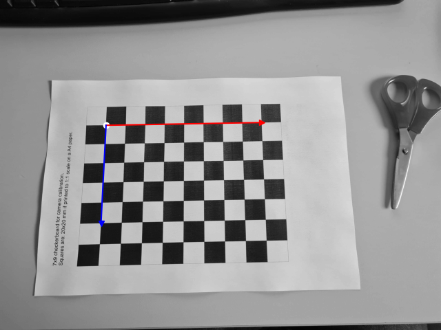
It includes a visualization of the location of its (3d) coordinate system assumed to be in the top-left corner, where the “left” side of the board is identified by the pattern description text. If we rotate the camera (or the pattern) by 180 degrees, the pattern itself looks almost identical:
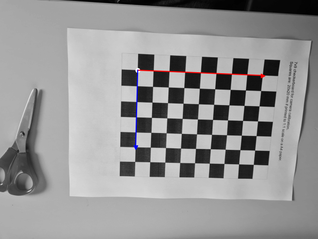
One can only tell that the camera has been rotated by looking at the additional objects in the scene (e.g., the scissors or the text printed onto the pattern), things that the pattern detector does not take into account, thus placing the coordinate system in the same location as in above image. As the calibration process hinges on correspondence between the coordinate system across the entire images series, this will lead to outliers in the data, negatively affecting the quality of the overall calibration result. The same holds true when using a calibration pattern with even number of inner corners.
However, one can circumvent this problem by choosing patterns with an even and odd combination of number of inner corners in the two directions. Then, the neighborhood of two opposing corners look different. Below is an example showing even number of inner corners in the \(x\)-direction and odd numbers of inner corners in the \(y\)-direction.
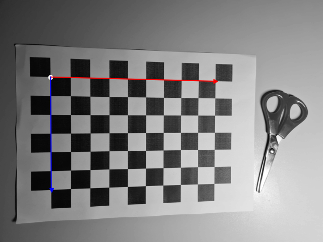
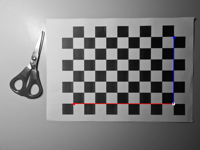
It is easy so see that if we erroneously placed the coordinate system in the top left (inner) corner of the right image above, the neighborhoods of both origins would look entirely different: a black square would be left above the origin in the first image, a white one in the second image.
In case, the pattern is mounted on the robot, make sure that it is planar, rigid, and tightly connected so that it does not move relative to the flange when going from one capture pose to the next. Any violation of the rigidity assumption will have negative impact on the calibration result.
Picking the Right Poses
Picking good poses is unfortunately a bit of an art, but here are some fundamental guidelines:
- In each pose, the checkerboard pattern on the calibration board must be completely visible by the camera.
- We recommend teaching no less than 40 different poses.
- Include different distances between camera and target.
- Include different orientations, in particular, rotations around the two sides of the pattern. Rotations around the normal of the pattern are less important.
- Make sure all regions of the image are hit by the pattern in some image of the sequence.
- Make sure there is a certain variability in the angular configurations of the robot even if some of the Cartesian positions are similar.
An example of a calibration sequence leading to highly accurate results is shown below:
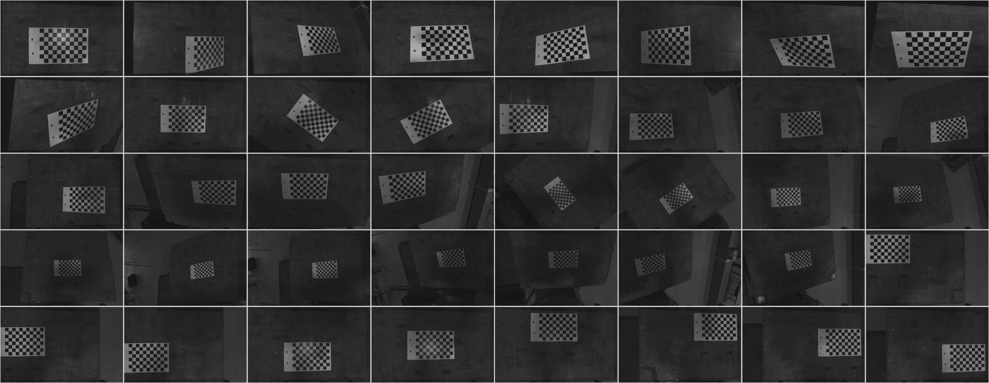
There is an excellent illustration of “good” poses available in the Zivid knowledge base.