Gripper Setup
Using the Frontend
Creating a New Gripper
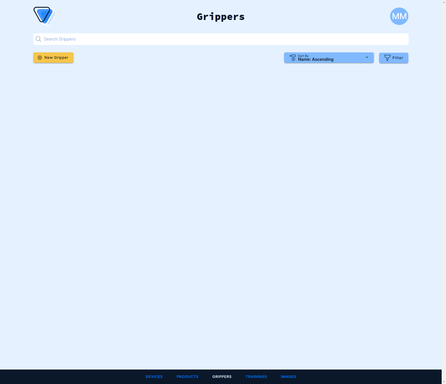
Log into the frontend at https://www.vathos.vision. Navigate to the Grippers tab in the menu on the bottom of the page and click New Gripper in the top left corner:
Enter all relevant information:
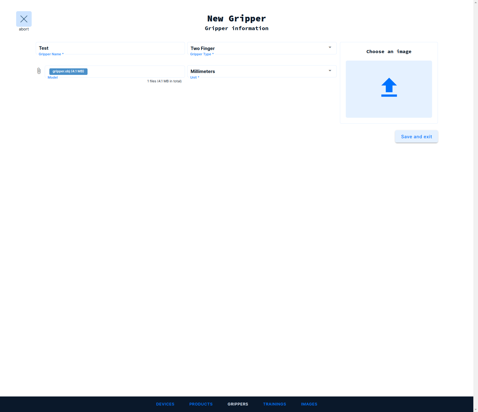
- Gripper Name: human-readable name of the gripper
- Gripper Type: functional principle of the gripper
- Model: (optional) a CAD model of your gripper
- Unit: units of measurement of the uploaded CAD model
- Image: (optional) a preview image of your gripper model
When you are done hit Save and Exit on the right. Now you can see the new gripper in the overview. Click on it to review and edit the information you have supplied:
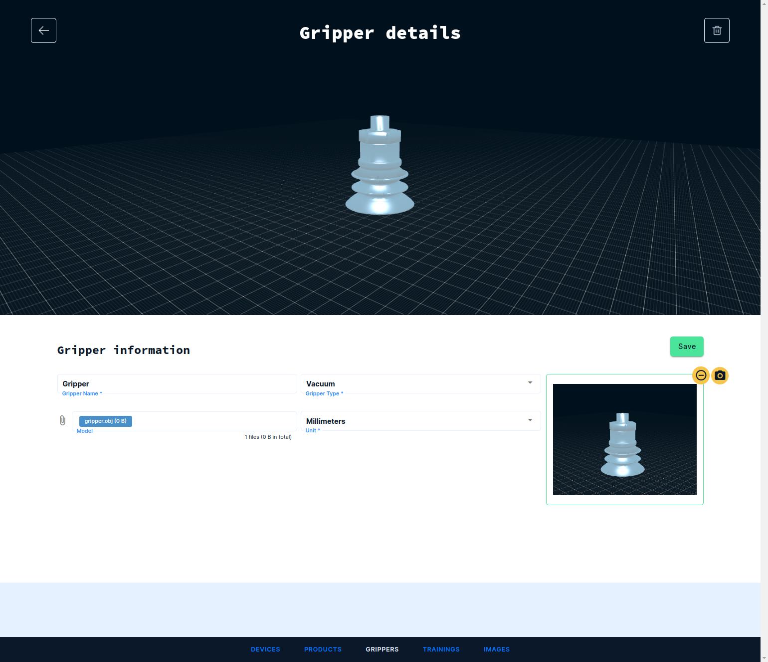
If you have attached a CAD model, you can render a thumbnail from it by clicking Edit, picking a desired vantage point by mouse inputs, and clicking on the little camera icon. Do not forge to hit Save to apply the changes.
CAD Model Preparation
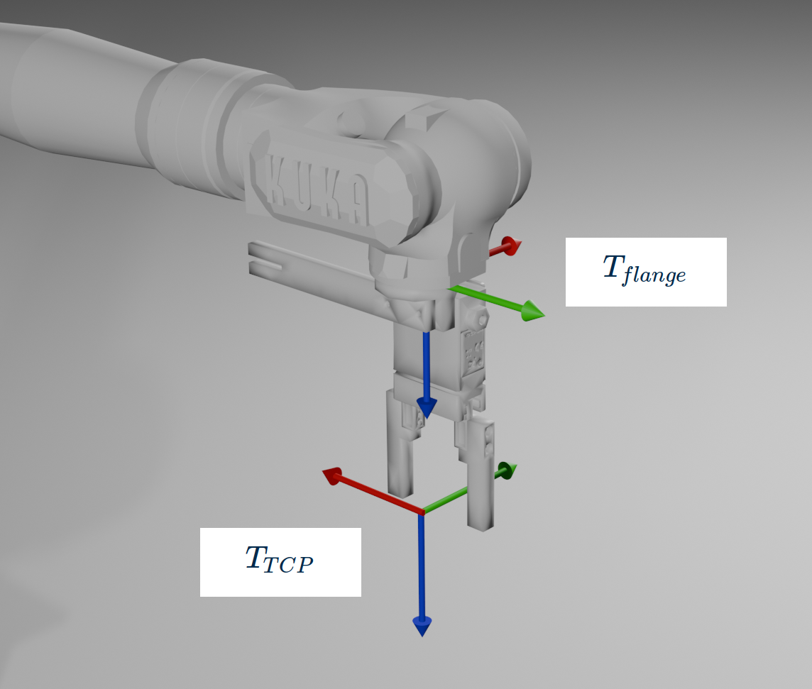
Our service do not maintain a full geometric model of the robot, thus it is not designed to do global collision avoidance. What it can do, and that is sufficient for many use cases, is check any part below the last joint of the robot for collisions. The uploaded CAD model should reflect the geometry of the tool sitting below the last joint also known as the flange. The only condition imposed on the CAD model besides being stored in OBJ format is that its inherent coordinate system, relative to which the mesh in the file is defined, matches the TCP coordinate system \(T_{TCP}\) that is later entered as tool data in the physical robot. If, e.g., the TCP sits between the tips of the two fingers of the gripper, then the coordinate system of the gripper CAD model should be just there.
Beware of non-trivial tool configurations where the \(T_{TCP}\) is not only shifted along the \(z\)-axis of the flange coordinate system \(T_{flange}\) but for example is rotated around that axis as well (see example image below). Make sure to check whether tool model coordinate system, tool definition on the robot controller, and physical mounting of the tool are all consistent, e.g., by jogging the robot in tool coordinates. A motion in positive x/y direction of the physical tool should match the positive x/y direction defined in the gripper model. The latter can be visualized with the help of the grip assignment wizard.
Assigning a Gripper to a Product
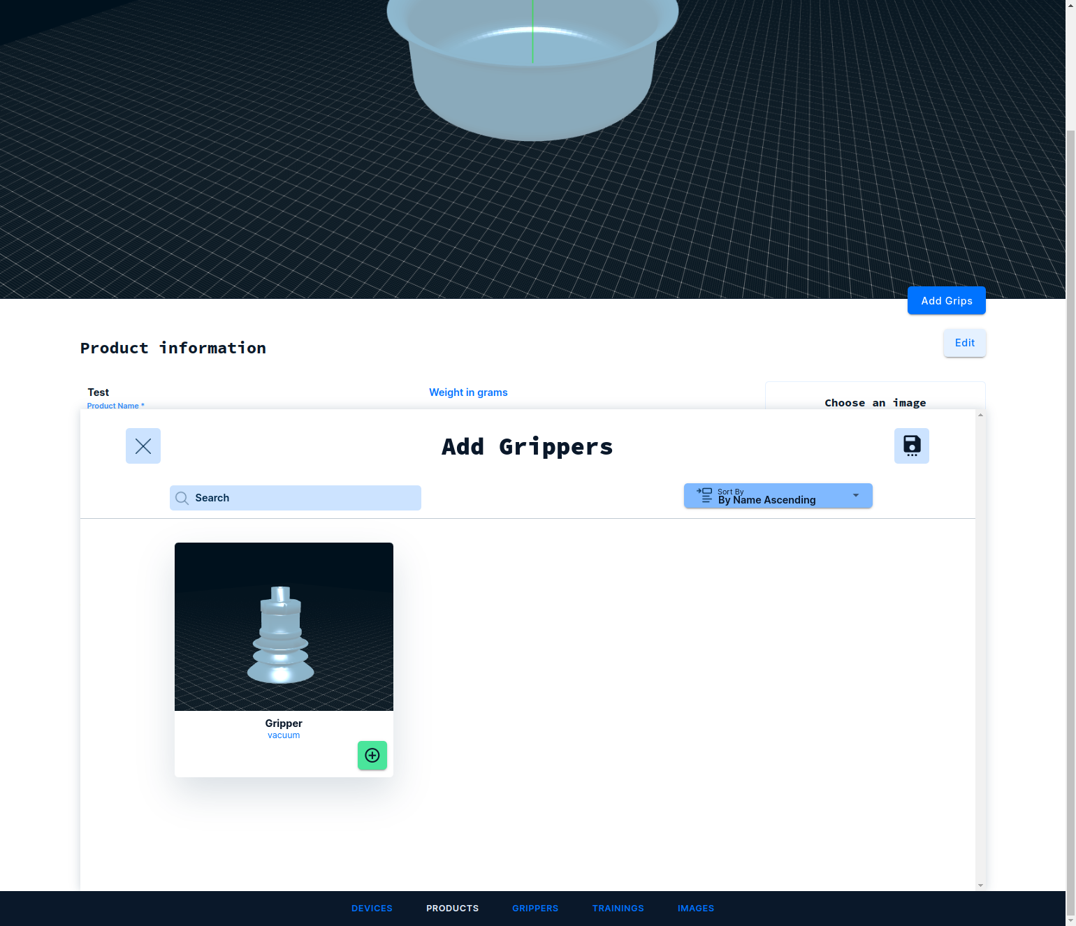
Click on Products in the bottom menu and select the product to which the gripper shall be assigned. On the product page, scroll down to Grippers and press the Add Grippers button:
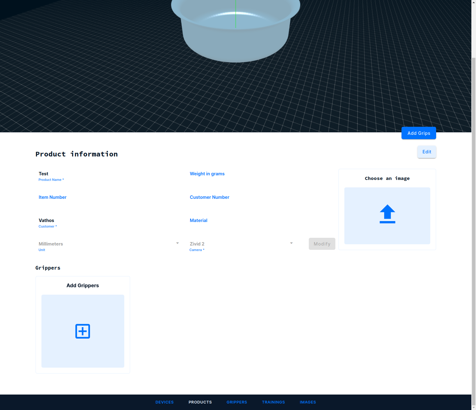
Add one (or more) grippers by pressing the green button and hit the Save icon in the top right corner, once you are done.