Digital I/O
Introduction
In applications where the client only needs to exchange very simple information (essentially, a list of bits) with any of our services, this communication can be established via digital inputs and outputs. Take for example a visual inspection task such as inline thermography where the client sends only a single bit to start image capture and retrieves a single bit from our service indicating whether the current image is OK or not OK. This of course requires that the edge device running our services is outfitted with a suitable IO interface. Currently, we support the following two devices:
- LucidControl USB module (recommended)
- On-board GPIO i2c device
Depending on our choice, make sure to install the corresponding driver app on the configuration page of your device:
1. LucidControl
The IO module from LucidControl is the recommended way for communication with other digital I/Os on the shop floor. One side hosts 4 digital outputs (DO0 - DO3), the other 4 digital inputs (DI0 - DI3):

The blue numbers added to the illustration above corresponds to the nomenclature used on the IO configuration page of the IR Inspect app:
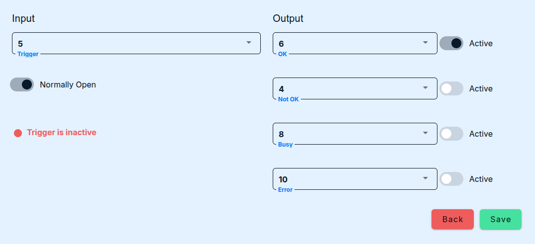
Each input/output consists of a pair of consecutive terminals, the first one of which can be connected to some +24V potential, the second one of which is connected to ground. When any of the outputs is set to a logical true, the module will short-circuit the corresponding terminals. Conversely, when the potential between two terminals of any input jumps from a value < 16V to a value in the range 21-31V, image acquisition and evaluation is triggered. Resetting the input level to a low level will not have any effect but is required for the detection of the next rising flank. The IO module itself is connected to any free USB port on the edge device. This ensures that the device is galvanically isolated from the higher voltage level used in OT.
Further information can be found in the owner’s manual.
2. GPIO
Alternatively, you can use the on-board GPIO interface on any of the Brick Silver models by our hardware partner spo-comm. The device delivery includes a suitable male plug whose 10 jacks we number consecutively from left to right.
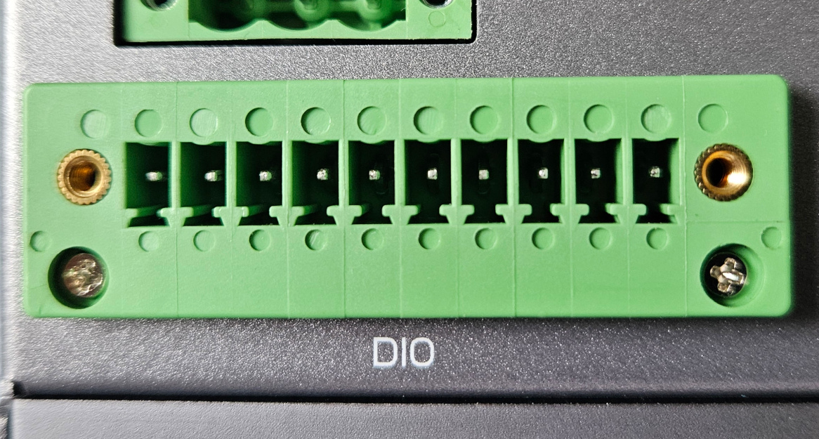

Each jack corresponds to a pin on the main board of the device with the following fixed functions:
| Pin No. | Function |
|---|---|
| 1 | +5V |
| 2 | Ground (GND) |
| 3 | Digital Input 1 (DI1) |
| 4 | Digital Output 1 (DO1) |
| 5 | Digital Input 2 (DI2) |
| 6 | Digital Output 2 (DO2) |
| 7 | Digital Input 3 (DI3) |
| 8 | Digital Output 3 (DO3) |
| 9 | Digital Input 4 (DI4) |
| 10 | Digital Output 4 (DO4) |
A digital input is triggered by connecting any of the four input pins (3, 5, 7, or 9) with ground (pin 2). Conversely, when our service signals true to some output, one will be able to measure a potential of +5V between the correponding pin (4, 6, 8, or 10) and ground (pin 2), 0V otherwise. There are two important things to consider when connecting any of the pins to an external device:
- The digital inputs behave like a NPN sensor, i.e., their value is
trueby default andfalsewhen they are grounded (connected to 2). - The GPIO card behind the pins operates on a +5V potential.
Under no circumstances, attempt to connect a 24V line directly to any of the input pins. This will result in irrecoverable damage to the main board of the edge device.
Connecting 24V I/Os
Inputs
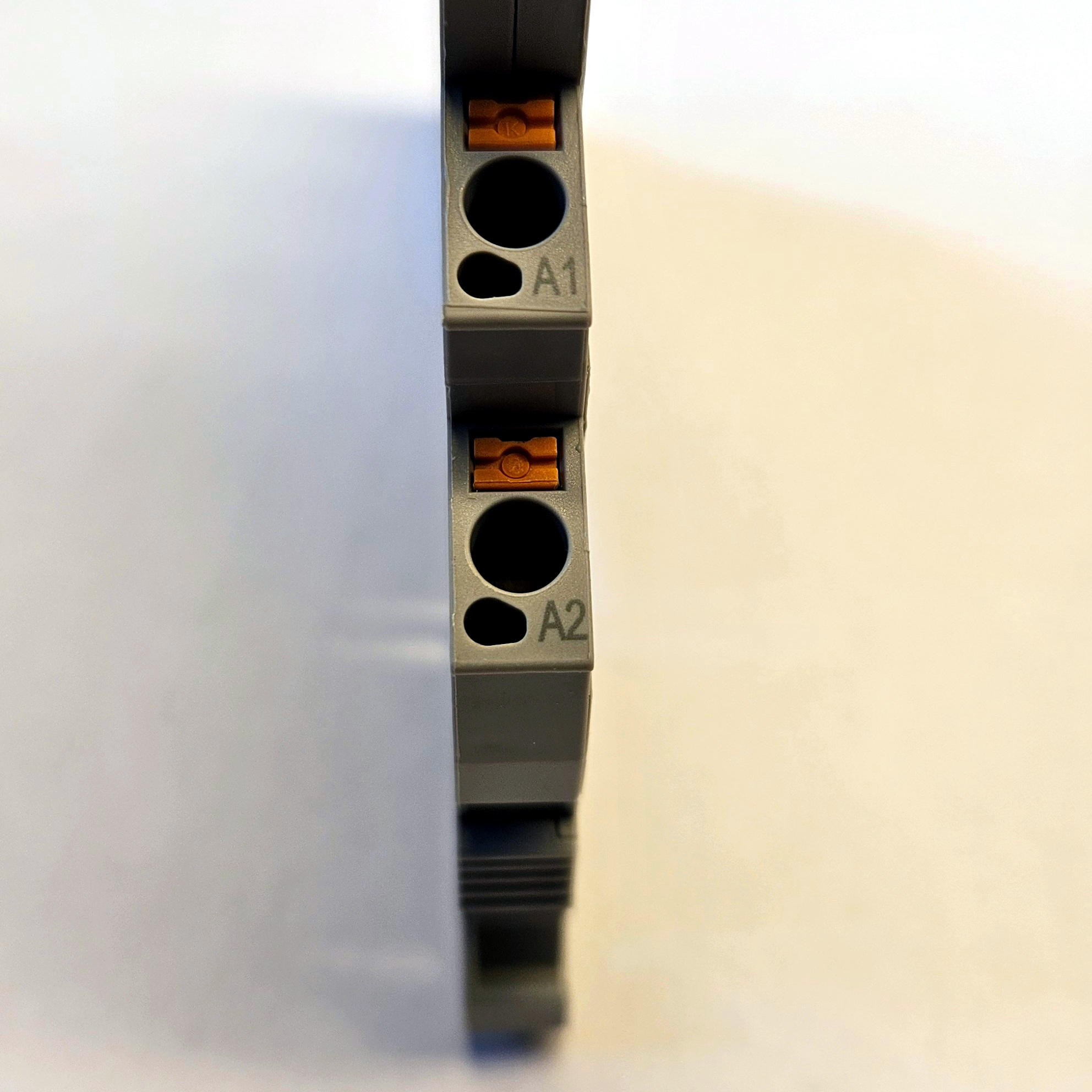
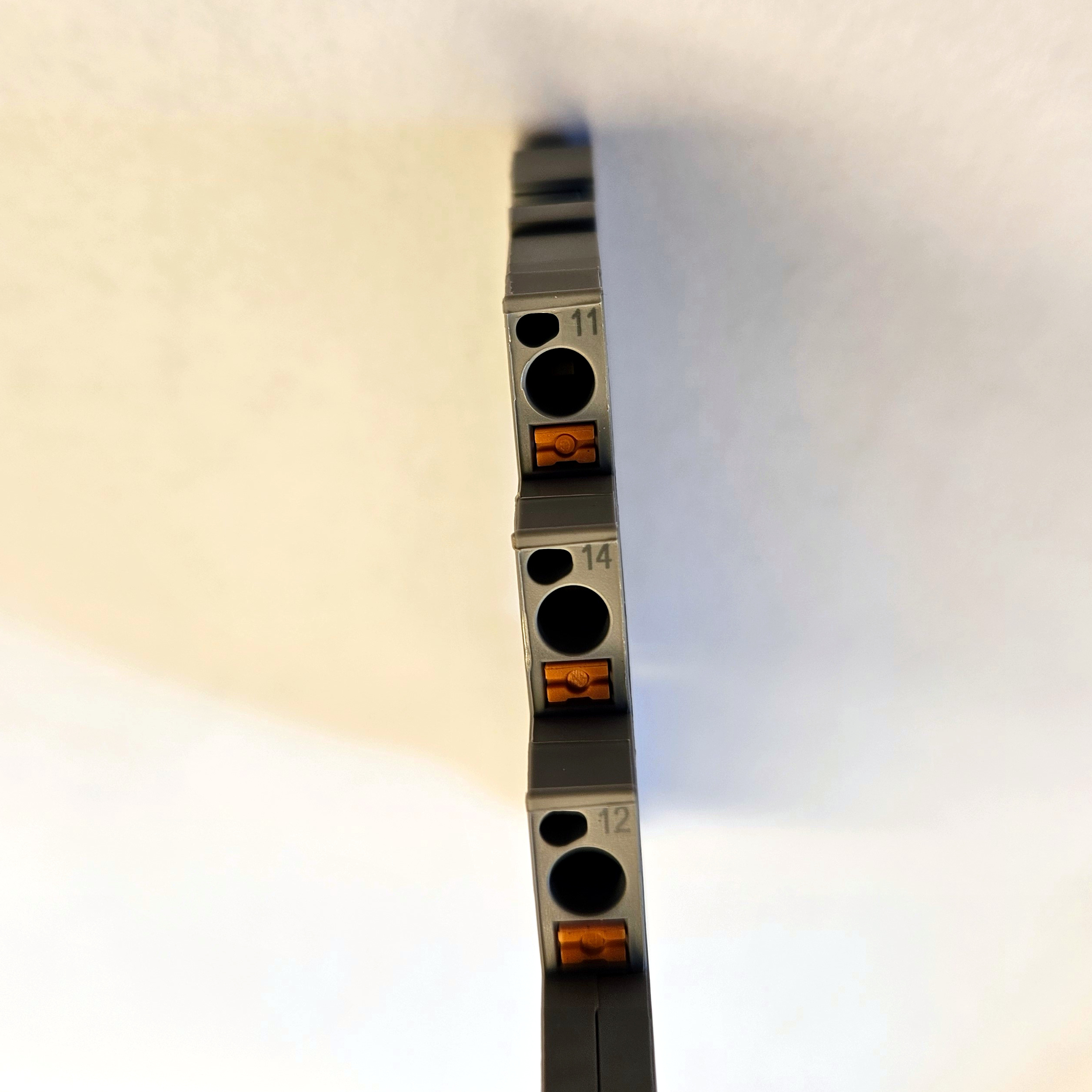
Using an coupling relay tolerating 24V or more of control voltage one can address both aforementioned issues by 1. flipping the input bit and 2. isolating the two voltage levels. Most coupling relays for industrial applications exhibit two ports on the control side named A1 and A2. First, connect the 24V output of the controller intending to send a trigger signal to A1 and controller ground to A2. Next, connect port 11 of the relay to input pin 2. There are two additional ports, 12 ane 14, on the load side of the relay. When the control input to the relay is true, the contact between 14 and 11 closes and the contact between 12 and 11 opens. To flip the input bit as desired, connect port 11 with the ground pin no. 2 and port 12 with one of the input pins 3, 5, 7, or 9.
Outputs
For sending outputs to the external controller/client, again a relay is needed to isolate the device voltage level from that of the controlled device. Connect the desired output pin (4, 6, 8, or 10) with A1 on the relay and pin 2 with A2. Presuming that the inputs of most industrial controller are normally open, connect port 14 of the relay with the controller input and pin 11 of the relay with controller ground.
The maximal current that can be drawn from any of the output pins is 0.6mA. If you are using passive relays to isolate the edge device from the +24V level on the load side, make sure that its state can be controlled with a very low-power signal (< 1mW). Alternatively, use an active relay which can draw additional power from pin number 1, which supplies ten times more current than any of the output pins.
Until recently, we shipped edge devices with an EGW-5200 CUSKIT DIO Module by Adlink. Thanks to built-in isolation, this module can communicate with 24V I/Os without needing to go through relays thanks to a set of built-in opto-couplers and the ability to connect an external power source. Correspondence between the relevant pins on the legacy connector with the physical pins described above is indicated by the blue numbers added to the illustration from the engineering specifications.  Note that the input pins are NPN, i.e., grounding one of the pins
 DIn_H by connecting it with GND_DIO (make sure to bridge the DIn_L pins and GND_DIO) will pull down the internal state to false, so make sure to configure the service being triggered to react to a falling flank of the signal. The output pins CN_DO_n are connected to the external +24V potential via the inputs on the controller reacting to the results of processing.